
CO2 Emission Tracking for Civil Engineering
Supports the industry to monitor and reduce CO2 emissions via digital tools.
CO2 Emission Data Collection
Algorithm Development for Emission Estimation

Web-Based CO2 Calculators
Zero-Emission Strategy Support

Frequently Asked Questions
CO2 emission tracking is the process of estimating and analyzing the carbon footprint generated throughout the lifecycle of a construction...
Tracking emissions gives you a clear understanding of your environmental impact...
We use industry-recognized methodologies, lifecycle assessment tools (LCA), material footprint analysis, and energy consumption data...
Lower emissions lead to reduced energy bills, improved efficiency, better compliance with green regulations...
CO2 emission tracking is valuable across all sectors — including civil works, infrastructure development...
Similar Projects
Discover more innovative projects:



Great
Solutions
Start With A ConversationGreat Solutions Start With A Conversation
Want to Explore How Our Services Can Grow Your Company?
CO2 Emission Tracking
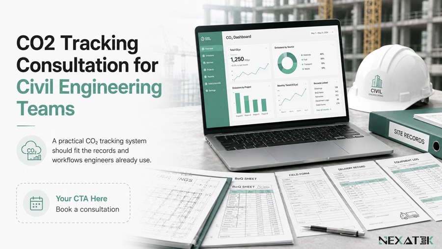
Concrete pours, excavator hours, aggregate haulage, and generator fuel all release carbon, yet few project teams can say how much. CO2 emission tracking closes that gap. The method converts physical construction activities into emission values, expressed in kilograms or tonnes of CO2, that engineers can compare and act on. NEXATEK builds this tracking around records civil engineers already maintain, such as the Bill of Quantities (BoQ) and daily equipment logs.
Carbon measured this way behaves like an engineering parameter, not a year-end estimate. A baseline built from project records shows which materials and which site practices drive the total.
CO2 Emission Tracking in Civil Engineering Projects
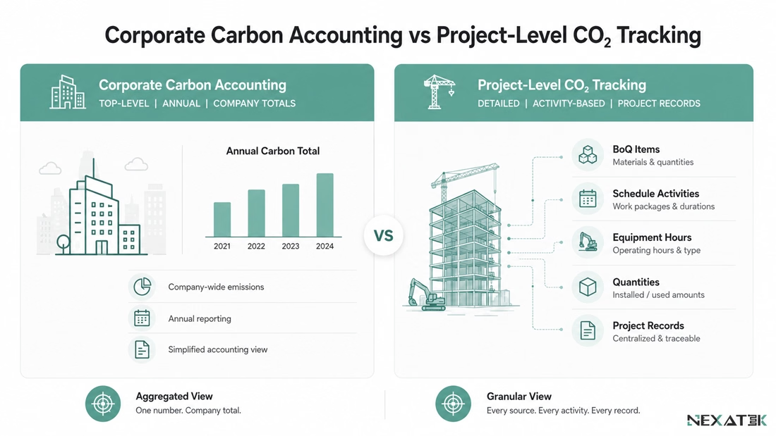
CO2 emission tracking in civil engineering quantifies the greenhouse gases released across an infrastructure project's lifecycle. Corporate carbon accounting works in annual company totals. Project-level tracking instead ties emissions to BoQ positions, schedule activities, and asset operating hours.
The granularity exists to support decisions. When a designer replaces Portland cement with a blend containing 35% ground granulated blast furnace slag, the embodied carbon of every cubic meter changes. Civil engineering emission measurement expresses that difference in tonnes of CO2, so carbon can sit next to cost and structural capacity as a design parameter.
Sources of CO2 Emissions in Civil Engineering
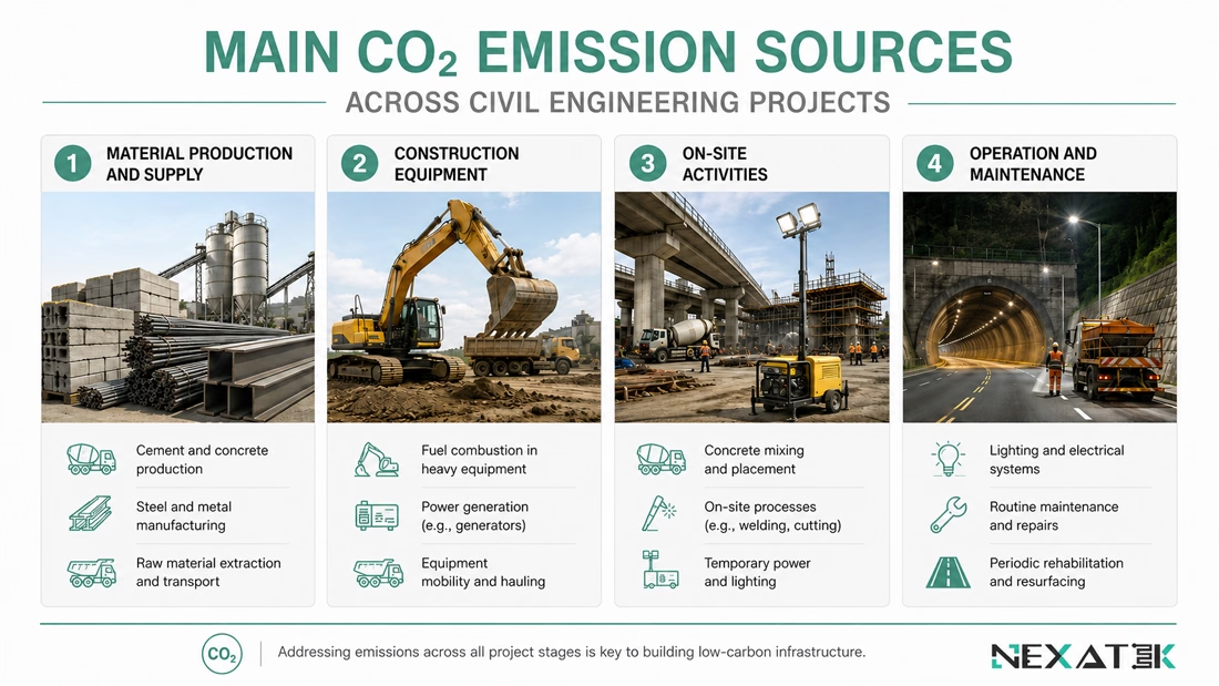
Two channels dominate: embodied carbon locked into materials and process emissions from construction and operation. Each channel needs its own data trail before any calculation starts.
Material Production and Supply
Materials usually carry the largest share of a project's footprint. Cement is the clearest case. Calcination releases CO2 from the limestone itself, and the kiln fuel adds a second stream on top.
Steel reinforcement brings its own production emissions, which vary with the share of recycled scrap in the melt. Transport adds more: hauling aggregate 120 km from a distant quarry raises the per-tonne factor compared with a local pit.
Construction Equipment and Machinery
Diesel plant produces direct, measurable emissions. A 25-tonne excavator burning around 18 liters of diesel per hour emits roughly 48 kg of CO2 in that hour. Duty cycle decides how the number accumulates, because a machine idling at the face still burns fuel without moving material.
Separating productive hours from idle hours sharpens both the carbon figure and the picture of site efficiency. Electric plant moves the emission to the power source, which changes the calculation rather than removing it.
On-site Construction Activities
Site overheads emit carbon outside the main works. Diesel generators powering offices and lighting often run at partial load, where fuel efficiency drops. Ground improvement contributes through its binders: lime and cement used for soil stabilization carry the same calcination emissions as any other cementitious material. Waste haulage and processing complete the construction carbon footprint at site level.
Operational and Maintenance Phases
Emissions continue after handover. Tunnel lighting, metro ventilation, and water treatment pumps draw energy for decades, and these operational emissions accrue against the asset rather than the contractor.
Maintenance adds recurring cycles of material and fuel. A highway repaved every 12 to 15 years consumes fresh asphalt and haulage each time. Across a 50-year design life, those interventions can approach the carbon of the original construction.
How CO2 Emission Tracking Works in Practice?
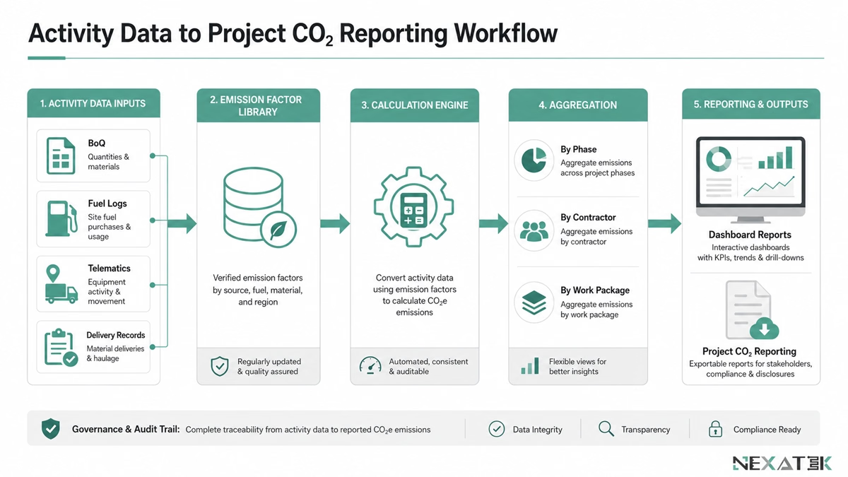
In practice, carbon emission tracking in construction runs in a fixed sequence. Activity data comes first. Emission factors then convert it into CO2 values, and aggregation rolls the results up for project teams.
Data Collection at Project Level
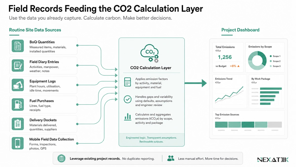
Most of the required data already exists. The BoQ states material volumes. Telematics and operator logs record equipment hours, while delivery dockets confirm haul distances and fuel purchases.
NEXATEK connects these streams so that carbon capture rides on routine reporting. When a site engineer approves a concrete pour in the daily diary, the system stores the volume and the mix design with it. Records entered on site through Mobile App Development reach the calculation layer without retyping.
Emission Calculation Logic
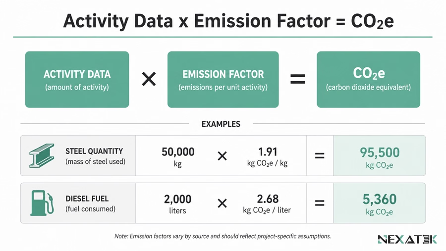
Conversion follows one formula: activity data multiplied by an emission factor equals emissions in CO2 equivalents. An emission factor states how much CO2 one unit of material or activity releases.
Two worked examples show the scale. Procuring 50,000 kg of structural steel at 1.91 kg CO2 per kg yields 95,500 kg of CO2. Burning 2,000 liters of diesel at 2.68 kg CO2 per liter yields 5,360 kg.
Factor selection decides accuracy. Values differ by region because electricity grids and manufacturing routes differ, and they shift over time as grids decarbonize. Factor libraries therefore belong in a dedicated emissions database that records the source and validity period of each value.
Aggregation Across Project Phases
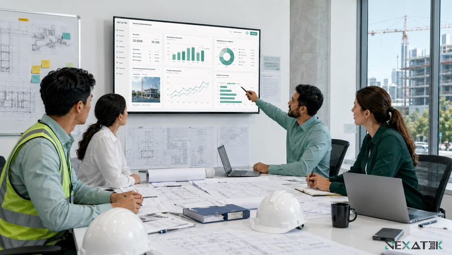
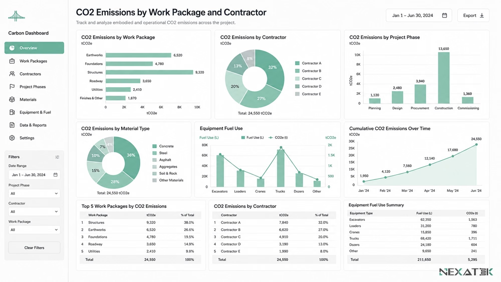
Raw calculations produce thousands of entries. Aggregation turns them into figures a project review can use, such as emissions by work package or by contractor. A manager can set Foundation Phase A against Foundation Phase B and trace the variance to ground conditions or plant selection. Portfolio rollups extend the same logic across several active sites.
CO2 Tracking Across the Civil Engineering Project Lifecycle
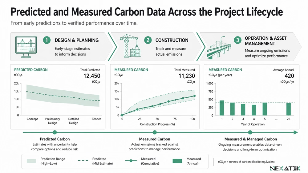
The character of carbon tracking in infrastructure development changes as a project advances. Early phases work with predicted values, and later phases replace them with measured ones.
Design and Planning Phase
Design-stage tracking is predictive. Quantities come from the model and factors come from libraries, because no site data exists yet. Engineering data for carbon analysis lets a team compare a steel composite deck against a post-tensioned concrete alternative, or weigh two road alignments. The output is a map of carbon hotspots: elements that contribute a disproportionate share of project lifecycle emissions, identified while specifications can still change.
Construction Phase
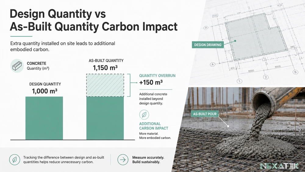
Measurement replaces prediction once works begin. Site teams track fuel consumption against the carbon budget and compare as-built quantities with the design. If drawings called for 1,000 cubic meters of concrete and 1,100 were poured, the extra 100 cubic meters carry a carbon penalty the design never included.
Live equipment data adds an early-warning function. A sudden rise in machine emissions points to excessive idling or a maintenance fault before the fuel invoices arrive.
Operation and Asset Management
After handover, CO2 monitoring for infrastructure projects narrows to energy use and maintenance cycles. The accumulated history supports repair-or-replace analysis. A road section that needs frequent, carbon-intensive patching can be compared on equal terms with a single deeper reconstruction.
Practical Applications for Civil Engineering Stakeholders
Stakeholders read the same emission data with different questions in mind.
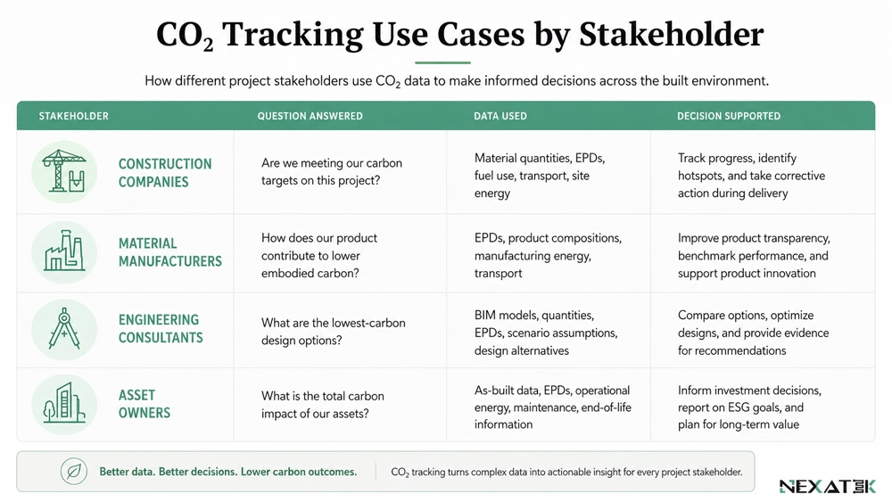
Use Cases for Construction Companies
Tenders increasingly ask for carbon reporting alongside price. A contractor holding project-level emission records can answer with measured data instead of estimates. The same records expose operational waste, since fuel burned and CO2 emitted rise together: shorter haul routes and correctly sized plant cut both.
Embedding the capture step into daily site reporting is an exercise in construction workflow automation. The diary entry that confirms a pour also logs its carbon value, so no parallel reporting chain is needed.
Use Cases for Material Manufacturers
Cement and steel producers use tracking to document the carbon intensity of their products. Material-based emission calculation feeds an Environmental Product Declaration (EPD), a published statement of a product's lifecycle impact.
A plant that switches kiln fuel or raises its recycled-scrap share can show the improvement as a lower declared factor. Engineers then specify materials against those declared values rather than generic industry averages.
Use Cases for Engineering and Consultant Firms
Consultancies use emission data to defend design decisions. When value engineering threatens a low-carbon option to save upfront cost, a quantified trade-off between cost and carbon keeps the discussion technical. NEXATEK supports this advisory work with methods grounded in applied engineering research, so factor choices and system boundaries remain documented and defensible.
Data Depth and Accuracy in Emission Tracking
Credible reporting rests on data quality, yet a live project produces far more records than anyone can verify line by line. Matching effort to impact keeps the system workable.
Level of Detail Required
Detail requirements differ by item. Concrete and reinforcing steel dominate embodied carbon on most structures and are typically tracked with supplier-specific factors or EPD values. Minor items such as fixings or signage rely on generic averages without shifting the total by more than a rounding error. Mixed fidelity concentrates verification effort where a 5% factor error would visibly move the result.
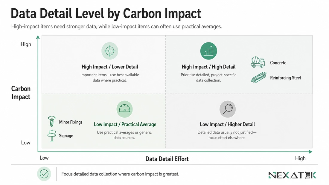
Balancing Accuracy and Practicality
Perfect accuracy is not achievable on an active site, and chasing it has a cost. A system demanding manual entry for every liter of fuel tends to fail through simple non-completion by site staff. Automated feeds from fuel cards or tank-level sensors deliver more consistent data, even when a single liter cannot be attributed to one task.
Trend direction carries most of the decision value. A dataset that stays comparable month after month shows whether emissions move up or down and which activities drive the change. Site decisions and design reviews consume that trend, not the fourth decimal place.